
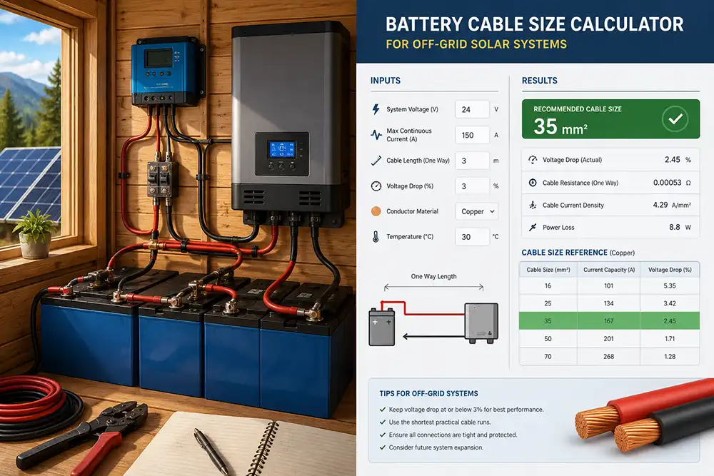
Choosing the correct wire and fuse size is the most important safety decision in an off grid solar system. Cables that are too thin overheat and waste power, and a missing or oversized fuse can turn a battery short into a fire. Battery banks can deliver thousands of amps in a fault, so every circuit needs a wire that fits the current and a fuse that protects that wire.
This guide shows how to pick wire and fuse size step by step. You will get a wire gauge chart, a voltage drop formula, fuse rules, and worked examples for a 12 V and a 48 V system. It is general education, not a replacement for local electrical code or a licensed electrician.
Wire and fuse size calculator
Planning estimate for copper cable. Ampacity values are typical figures for insulated copper in free air; check your cable manufacturer and local electrical code before installing.
The two rules for wire and fuse size
- The wire must carry the maximum continuous current without overheating (ampacity).
- The fuse or breaker must be smaller than the wire ampacity, but larger than the normal load current, so it trips before the wire is damaged.
A third rule applies to long runs: keep voltage drop low, usually under 2 to 3 percent for the battery and inverter circuits. Voltage drop wastes energy and can cause inverter low-voltage shutdowns.
Step 1: Find the maximum current
Current equals power divided by voltage. For an inverter, use the maximum continuous watts divided by the lowest battery voltage and efficiency.
- Inverter current = inverter watts / (battery voltage x 0.85).
- Solar array current = array watts / battery voltage (or the controller rated output current).
- Add a 25 percent safety margin for continuous loads, as electrical code commonly requires.
Example: a 2,000 W inverter on a 12 V battery draws 2,000 / (12 x 0.85) = about 196 A. With a 25 percent margin, design for about 245 A. This is why large inverters run on 24 V or 48 V systems: a 48 V system draws only one quarter of the current for the same power. If you are still deciding on size, use our inverter size calculator.
Step 2: Choose the wire gauge
The table shows approximate copper wire ampacity at 75 degrees Celsius insulation rating, based on common US (AWG) values. Always check the tables of your own country and the insulation rating of your cable, and derate for high ambient temperatures or bundled cables.
| Wire size (AWG) | Approx. ampacity (A) | Typical maximum fuse (A) | Typical use |
|---|---|---|---|
| 14 | 20 | 15 | Small lights, sensors |
| 12 | 25 | 20 | Small DC loads, PV strings |
| 10 | 35 | 30 | Solar panel strings, small controllers |
| 8 | 50 | 40 | Charge controller output |
| 6 | 65 | 60 | Small inverters, 60 A controllers |
| 4 | 85 | 70 to 80 | 1,000 W inverter at 12 V |
| 2 | 115 | 100 | 24 V inverters |
| 1/0 | 150 | 125 to 150 | 2,000 W at 24 V or 3,000 W at 48 V |
| 2/0 | 175 | 150 to 175 | Large 48 V inverters |
In Europe, cables are sized in square millimetres. As a rough guide, 4 mm² is about 12 AWG, 10 mm² is about 8 AWG, 25 mm² is about 4 AWG and 50 mm² is about 1/0 AWG. Use the ampacity table of the cable manufacturer.
Step 3: Check the voltage drop
Voltage drop in percent equals 2 x length x current x resistance per length, divided by the system voltage, then multiplied by 100. Length is the one-way distance, because current flows out and back.
| Wire (AWG) | Resistance (ohm per 1,000 ft) |
|---|---|
| 10 | 0.999 |
| 8 | 0.628 |
| 6 | 0.395 |
| 4 | 0.249 |
| 2 | 0.156 |
| 1/0 | 0.098 |
| 2/0 | 0.078 |
Example: a 12 V circuit carrying 40 A over 10 ft one way, with 4 AWG wire. Resistance is 0.249 x 20 / 1,000 = 0.005 ohm. Voltage drop is 0.005 x 40 = 0.2 V, or 1.7 percent of 12 V. With 10 AWG wire, the drop is 0.8 V, about 6.7 percent, which is too high. Low voltage systems need thick cable and short runs.
Step 4: Choose the fuse or breaker
Place a fuse as close to the battery positive terminal as possible, on every positive conductor leaving the battery. The fuse protects the cable, not the device.
- Battery to inverter: use a Class T or MRBF fuse rated for DC and for the battery short circuit current.
- Solar panels: use DC-rated breakers or fuses, not standard AC breakers.
- Charge controller: fuse on both the battery side and the PV side, sized to 125 percent of rated current.
- Always use a DC-rated disconnect near the battery to isolate the bank for service.
The fuse must have an interrupt rating higher than the available fault current of the battery bank. Lithium batteries can deliver very high currents, so check the battery data sheet and use fuses like Class T with a 20,000 A interrupt rating.
Worked example: 48 V, 3,000 W inverter
- Inverter current: 3,000 / (48 x 0.85) = about 74 A.
- With a 25 percent margin: about 92 A.
- Choose 1/0 AWG? Not needed. 2 AWG (115 A) already exceeds 92 A.
- Choose a 100 A Class T fuse, below the 115 A wire ampacity.
- Check the drop: 8 ft one-way x 92 A with 2 AWG gives about 0.23 V, which is 0.5 percent of 48 V.
The same 3,000 W on a 12 V system would draw nearly 300 A and require very thick cable. That is why the system voltage matters so much. See our guide on solar panels in series vs parallel for how string voltage affects the PV wiring.
Common wire and fuse mistakes
- Using AC breakers on DC circuits. They cannot safely interrupt DC arcs.
- Fuse too close to the wire rating, with no safety margin.
- Skipping the fuse on the battery positive.
- Using flexible cable with small crimped lugs. Use properly crimped, tinned copper lugs and a hydraulic or heavy crimp tool.
- Mixing wire colors. Use red for positive and black for negative consistently.
- Long thin runs between panels and controller in a low-voltage array.
Related guides
- Inverter Size Calculator for Off-Grid Solar
- 12V vs 24V vs 48V Solar System
- MPPT Charge Controller Sizing Calculator
- Camper Van Electrical System Calculator
Frequently Asked Questions
What wire size do I need for a 12 V 100 A circuit?
About 2 AWG copper for short runs under 10 ft, with a 125 A rated fuse chosen below the wire ampacity. Longer runs need thicker wire to limit voltage drop.
Where should the main battery fuse go?
As close as possible to the battery positive terminal, ideally within 7 inches or 18 cm, so that the whole cable is protected.
Can I use a normal household breaker for solar panels?
No. Use breakers and fuses rated for DC voltage and the open-circuit voltage of your array, because DC arcs are harder to extinguish than AC arcs.
Is thicker wire always better?
Thicker wire reduces voltage drop and heat, but it costs more and is harder to terminate. Choose the size that meets ampacity and voltage drop targets, then protect it with the right fuse.
Sources and further reading
- NFPA 70: National Electrical Code
- U.S. Department of Energy: Solar for homeowners
- NREL: Solar research and guidance
Getting wire and fuse size right takes a few minutes of math and prevents the most common solar fires. Calculate the current, pick a wire with enough ampacity, check the voltage drop, protect it with a DC-rated fuse near the battery, and have a qualified electrician review the final design.
3 thoughts on “Wire and Fuse Size for Off Grid Solar: DC Cable, Breaker and Fuse Chart”
Comments are closed.